

In a stirred-tank bioreactor, the flow pattern is largely defined by the impeller design. That pattern determines how liquid circulates, how gas is dispersed, how quickly the vessel becomes homogeneous and how much local shear the culture experiences.
The three most common reference patterns are radial flow, mixed axial-radial flow and axial flow. In practice, these are closely linked to Rushton, pitched-blade and hydrofoil impellers. Choosing the right pattern is not only a fluid-dynamics question, it is a process decision that directly affects mixing, oxygen transfer and cell protection.
Flow pattern is one of the key process variables in a stirred bioreactor because it shapes circulation, shear and gas-liquid performance throughout the tank.
What is a flow pattern in a stirred-tank bioreactor?
In a stirred-tank bioreactor, the flow pattern is the dominant circulation path created by the impeller inside the vessel. It describes how the liquid moves, mainly axial, radial or mixed, and directly affects mixing time, gas dispersion, local shear and how quickly the tank becomes homogeneous.
That is why flow pattern should be treated as a core process variable. It influences not only bulk mixing but also the microscopic environment experienced by cells or microorganisms.
A bioreactor can have the right volume and control system and still perform poorly if the internal flow pattern does not fit the biology.
Rushton impeller, radial flow and high shear
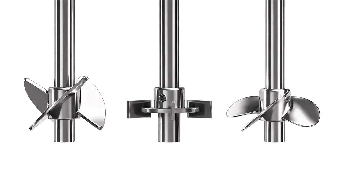
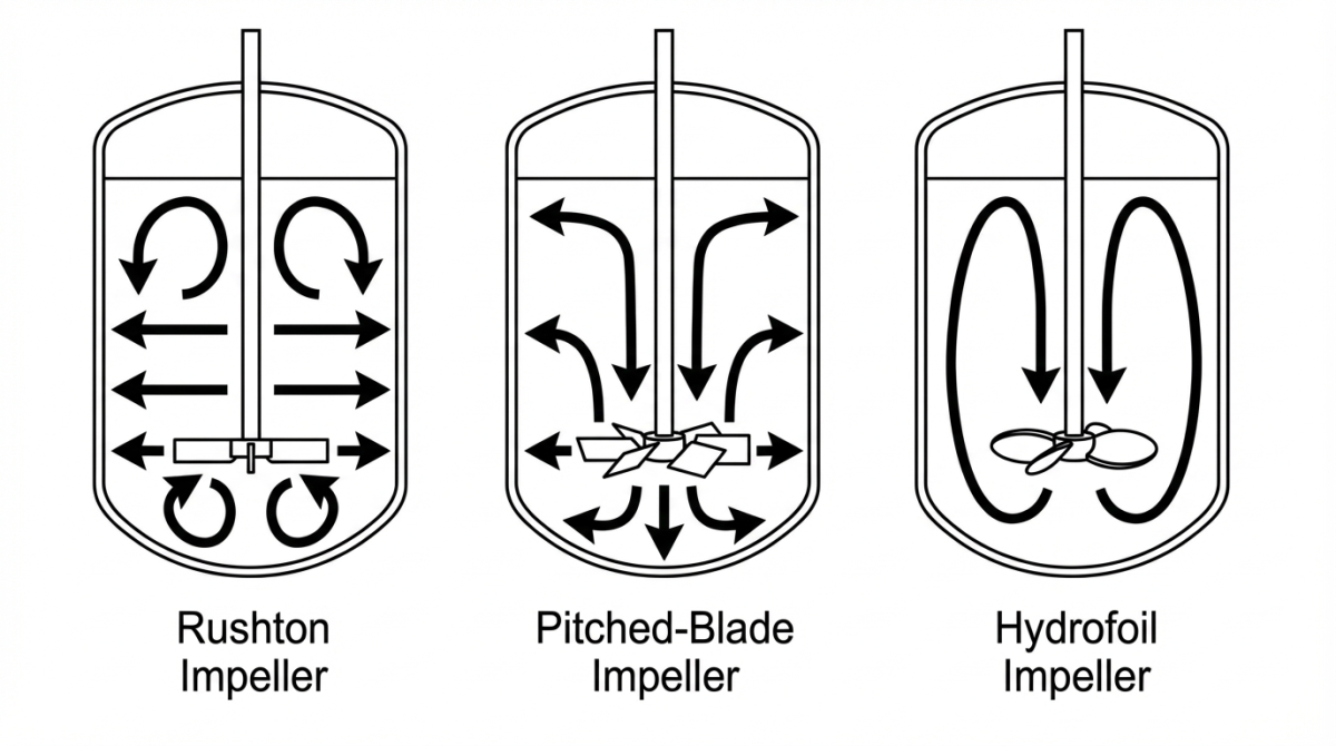
A Rushton turbine is a flat disk with 4 to 6 vertical blades. It generates a predominantly radial flow pattern, meaning the liquid is pushed sideways toward the vessel wall. In baffled tanks, that radial jet then splits into two circulation loops, one above and one below the impeller plane.
Radial, with a strong horizontal discharge toward the wall.
Very effective gas dispersion and strong bubble breakup.
High local shear and higher energy demand compared with axial-flow alternatives.
Rushton turbines are usually preferred in aerobic microbial fermentations where organisms tolerate shear and oxygen transfer is prioritized.
Pitched-blade impeller, mixed axial-radial flow
A pitched-blade impeller consists of flat blades mounted at an angle, commonly around 45 degrees. This geometry creates a mixed axial-radial flow because the discharge leaves the blades diagonally instead of purely sideways or purely vertical.
Mixed axial-radial, supporting both vertical circulation and lateral redistribution.
Balanced mixing with lower shear than a Rushton turbine.
Usually delivers lower absolute gas dispersion than Rushton at the same power input.
Pitched-blade impellers are widely used in cell culture and general-purpose mixing where the process needs a compromise between oxygen transfer and gentler hydrodynamics.
Hydrofoil impeller, axial flow and low shear mixing
Hydrofoil impellers are designed with curved blades that create a predominantly axial flow pattern. They move large fluid volumes vertically with relatively low power input, which makes them especially attractive for low-shear and energy-efficient mixing strategies.
Axial, with strong vertical circulation through the vessel.
High pumping efficiency and low local shear.
Absolute gas dispersion is often lower than Rushton if the only target is maximum bubble breakup.
Hydrofoil impellers are usually recommended for shear-sensitive cell cultures, gentle scale-up strategies and higher-viscosity media.
Flow pattern comparison of common bioreactor impellers
The main differences between Rushton, pitched-blade and hydrofoil impellers can be summarized in practical process terms.
| Feature | Rushton | Pitched-blade | Hydrofoil |
|---|---|---|---|
| Flow pattern | Radial, strong horizontal jet | Mixed axial-radial, diagonal discharge | Axial, strong vertical pumping |
| Main circulation | Two toroidal loops above and below the impeller | Large mixed loop depending on blade orientation | Clean vertical circulation loop |
| Best at | Bubble breakup and gas dispersion | Versatile bulk mixing | Efficient low-shear circulation |
| Shear near blades | High | Moderate | Low |
| Gas dispersion / oxygen transfer | Very high | Good | Good relative to power input |
| Energy efficiency | Lower | Intermediate | Higher |
| Typical use | Aerobic microbial fermentation | Cell culture and general-purpose mixing | Shear-sensitive cultures and gentle scale-up |
Shear, mixing and oxygen transfer in bioreactor flow patterns
Flow pattern is important because it changes the balance between mixing quality, oxygen transfer and local mechanical stress. Radial-flow impellers such as Rushton usually deliver stronger bubble breakup and often the highest oxygen-transfer values, but they also create stronger local turbulence.
Axial-flow impellers such as hydrofoils often provide more efficient bulk circulation and lower shear at lower power input. Mixed-flow pitched-blade designs sit between those two extremes, which is why they are so commonly used in balanced process environments.
There is rarely a perfect flow pattern in general, only the flow pattern that best fits the biological and engineering priorities of the process.
Choosing the right flow pattern by culture type
Culture type is one of the clearest selection criteria. Robust microbial organisms usually tolerate higher shear and often need more oxygen transfer, while mammalian and other delicate cell cultures usually benefit from gentler hydrodynamics.
Often work well with Rushton-type radial flow because oxygen transfer is critical and shear tolerance is higher.
Usually perform better with pitched-blade or hydrofoil designs that reduce local turbulence.
Hydrofoil impellers can be especially useful because they circulate large volumes efficiently with lower power demand.
Impeller geometry and flow pattern should be matched to the real culture, not chosen from a rule of thumb alone.
How TECNIC fits this workflow
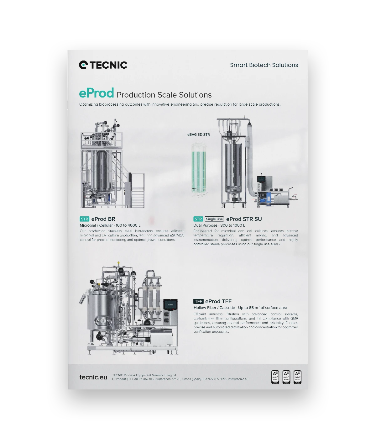
TECNIC fits this topic directly because its bioreactor platforms support both microbial and cell-culture processes where flow pattern, agitation logic and oxygen-transfer strategy need to be adapted to the biology and to the chosen scale-up path.
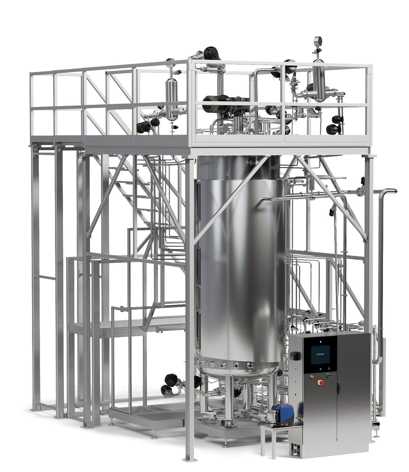
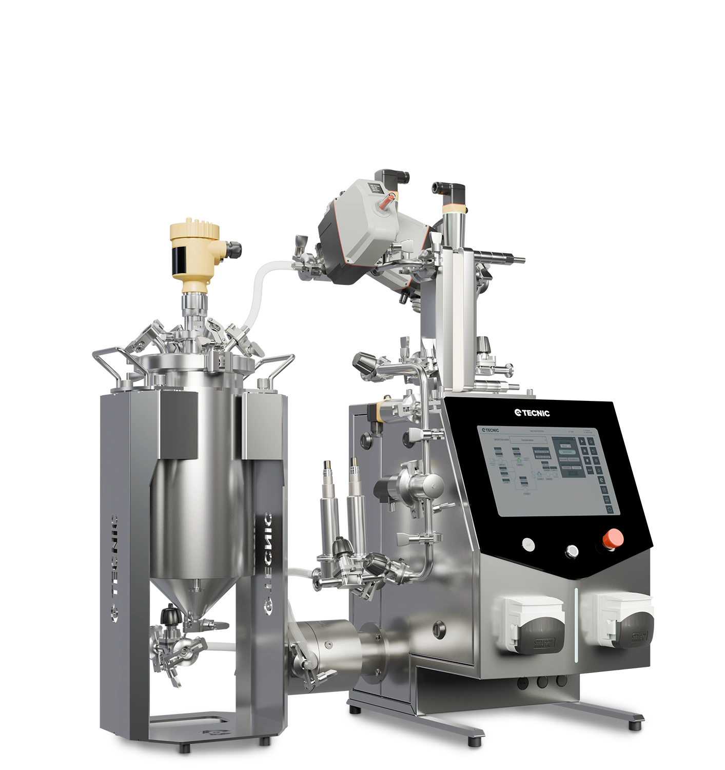
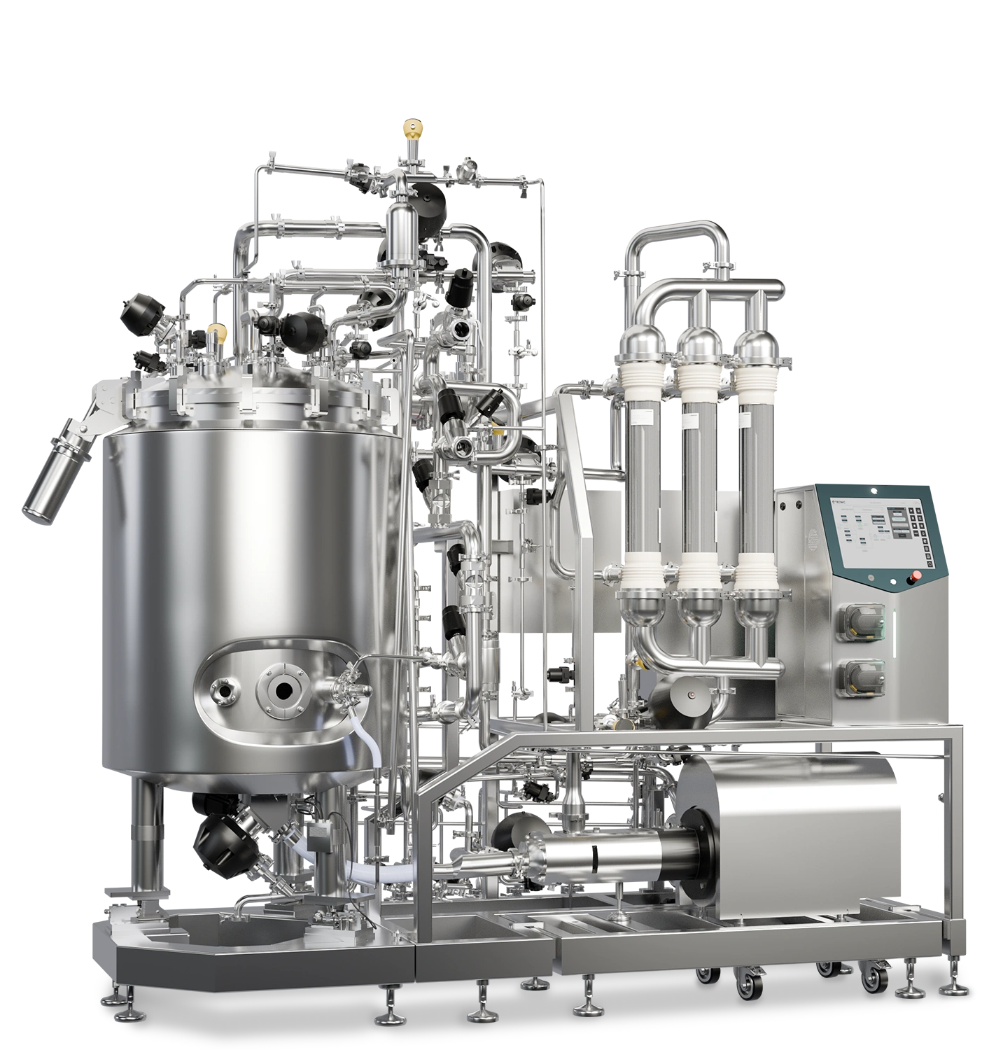
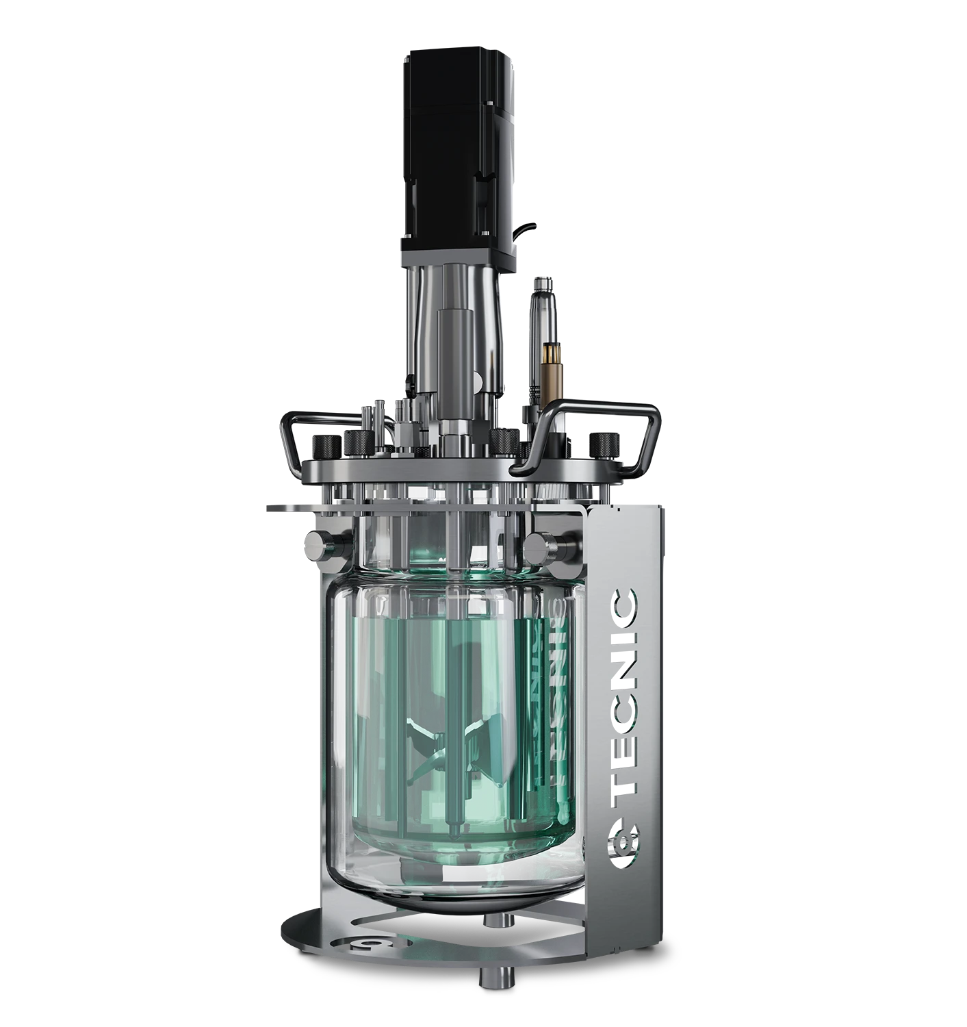
Bioreactors
Relevant when internal circulation, gas dispersion and shear environment need to be aligned with process requirements.
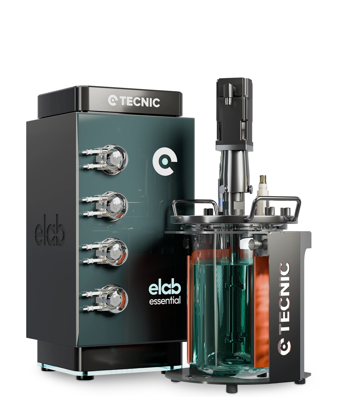
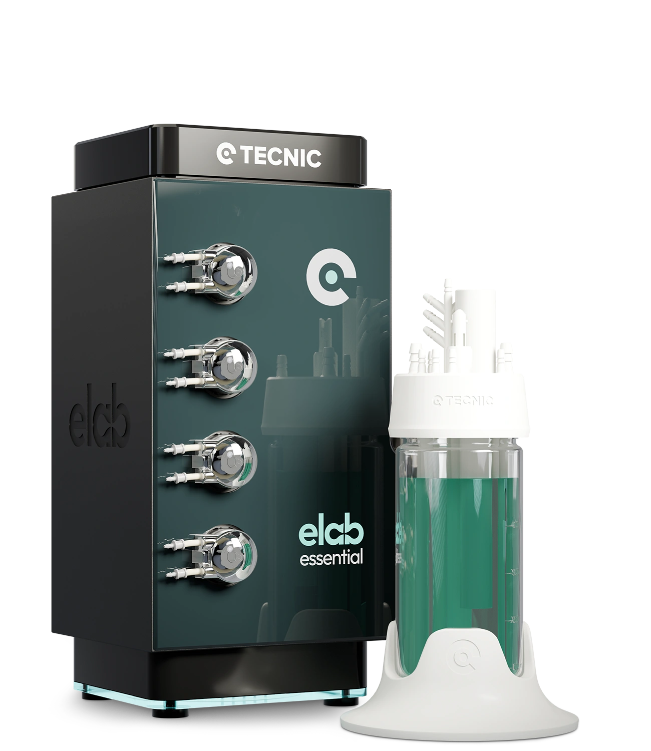
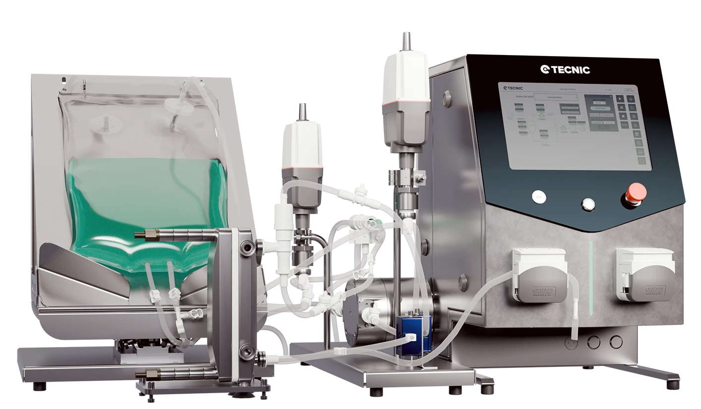
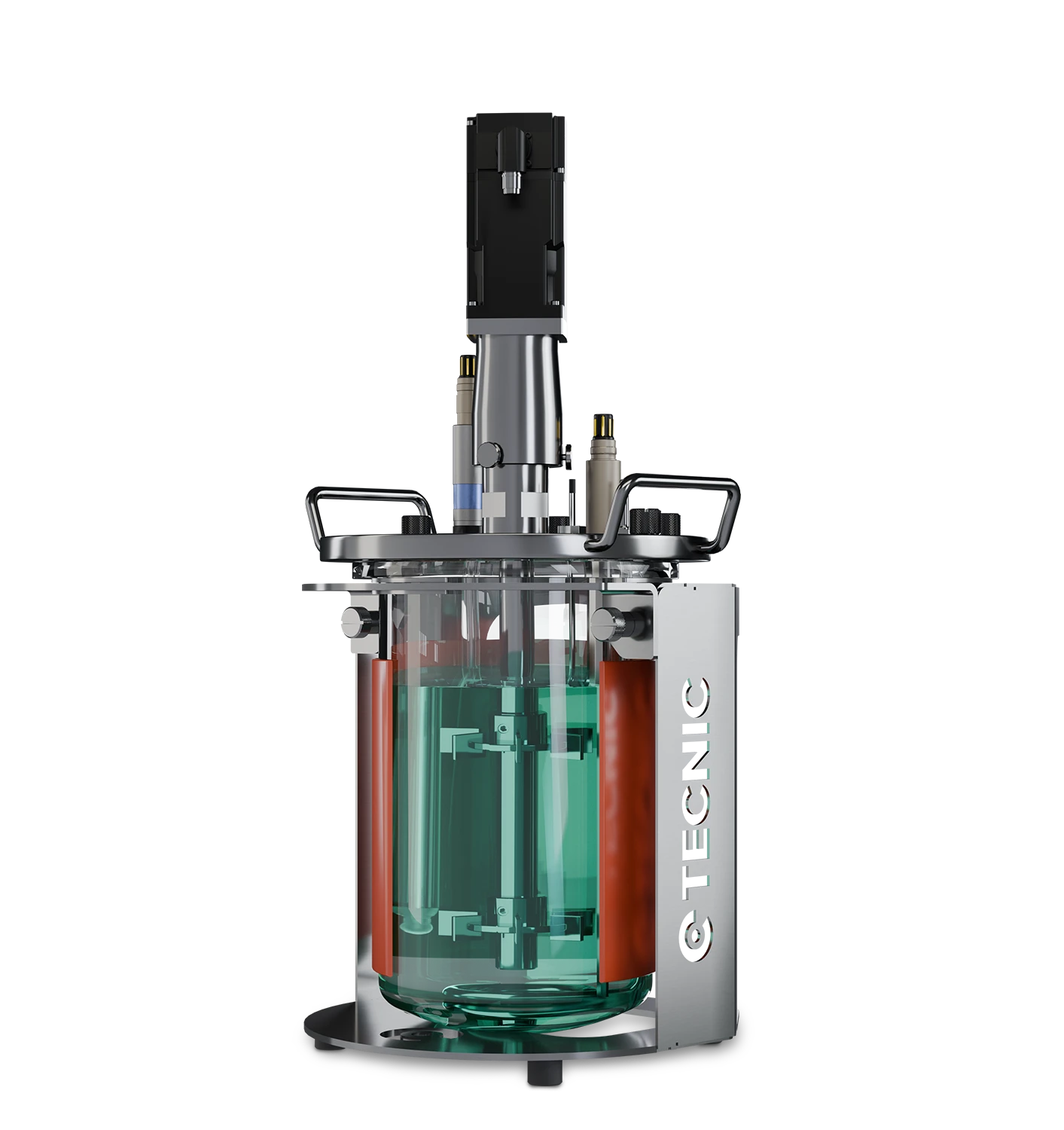
eLab Advanced
Useful where flow-pattern decisions are still being studied during development and early process definition.
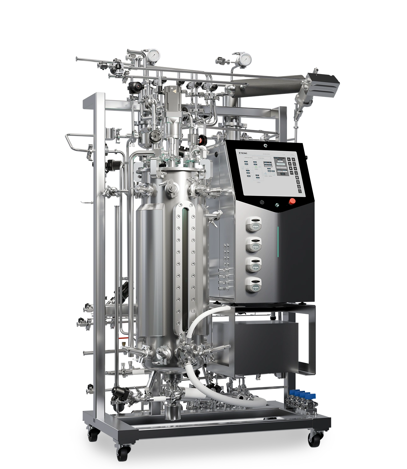
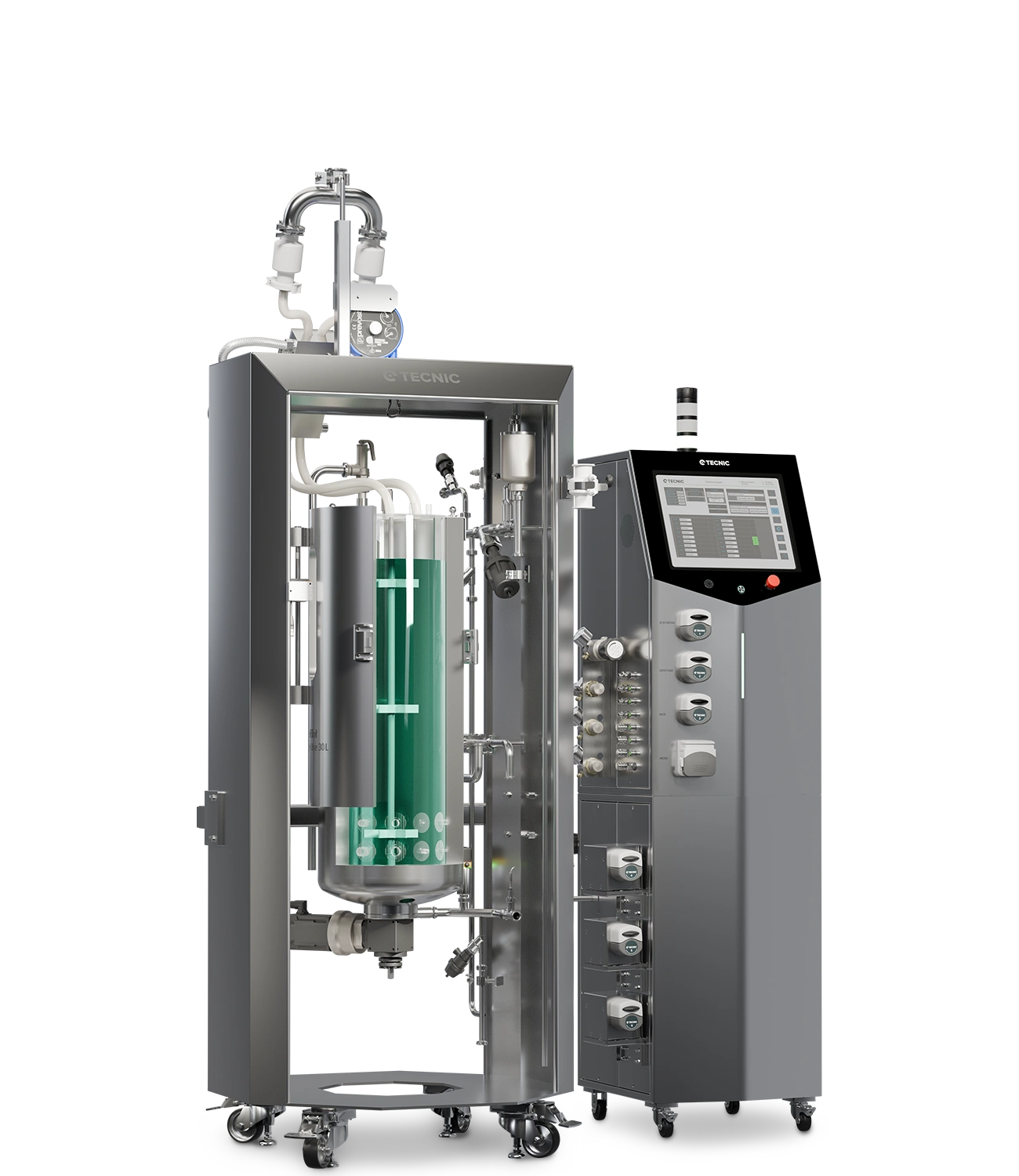
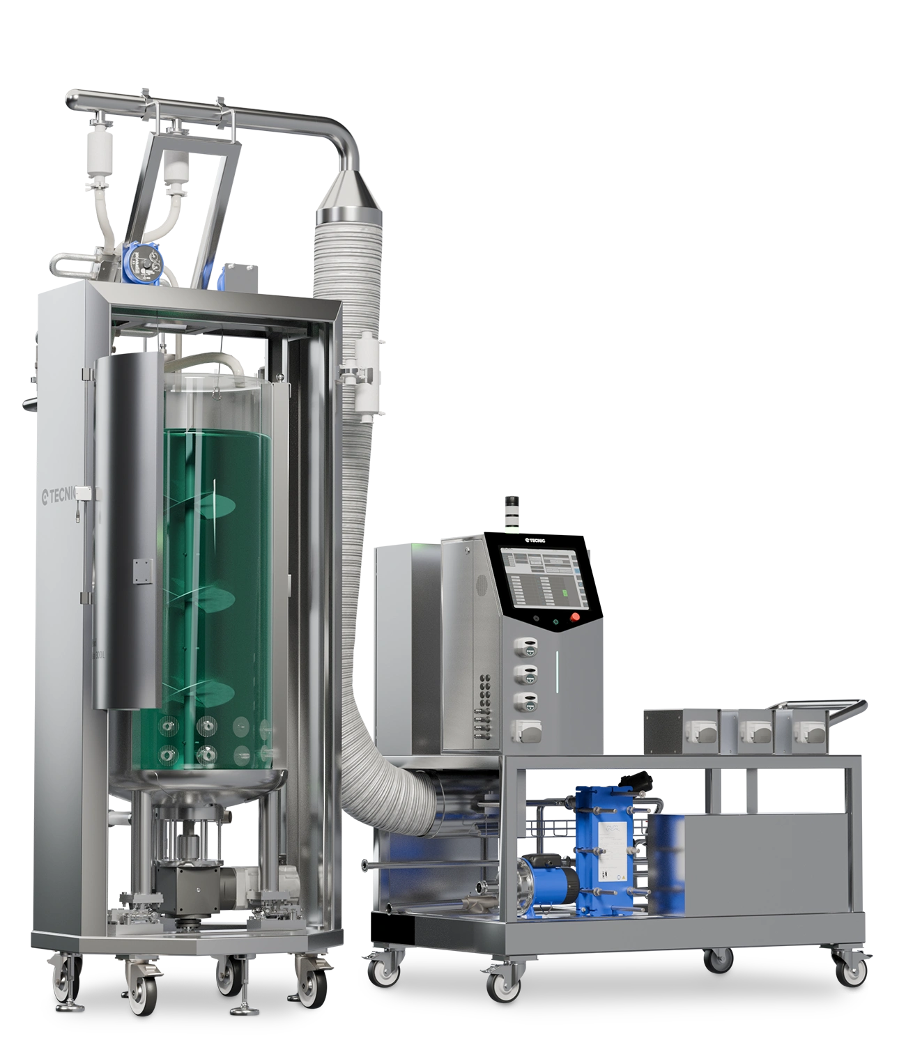
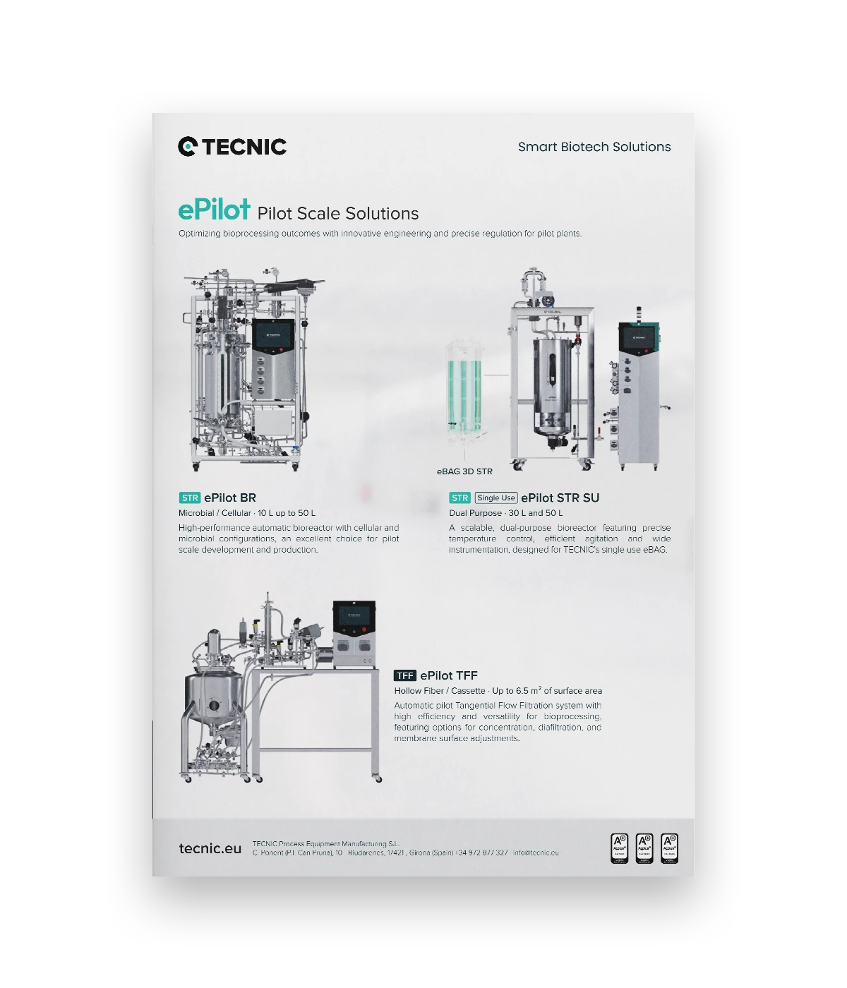
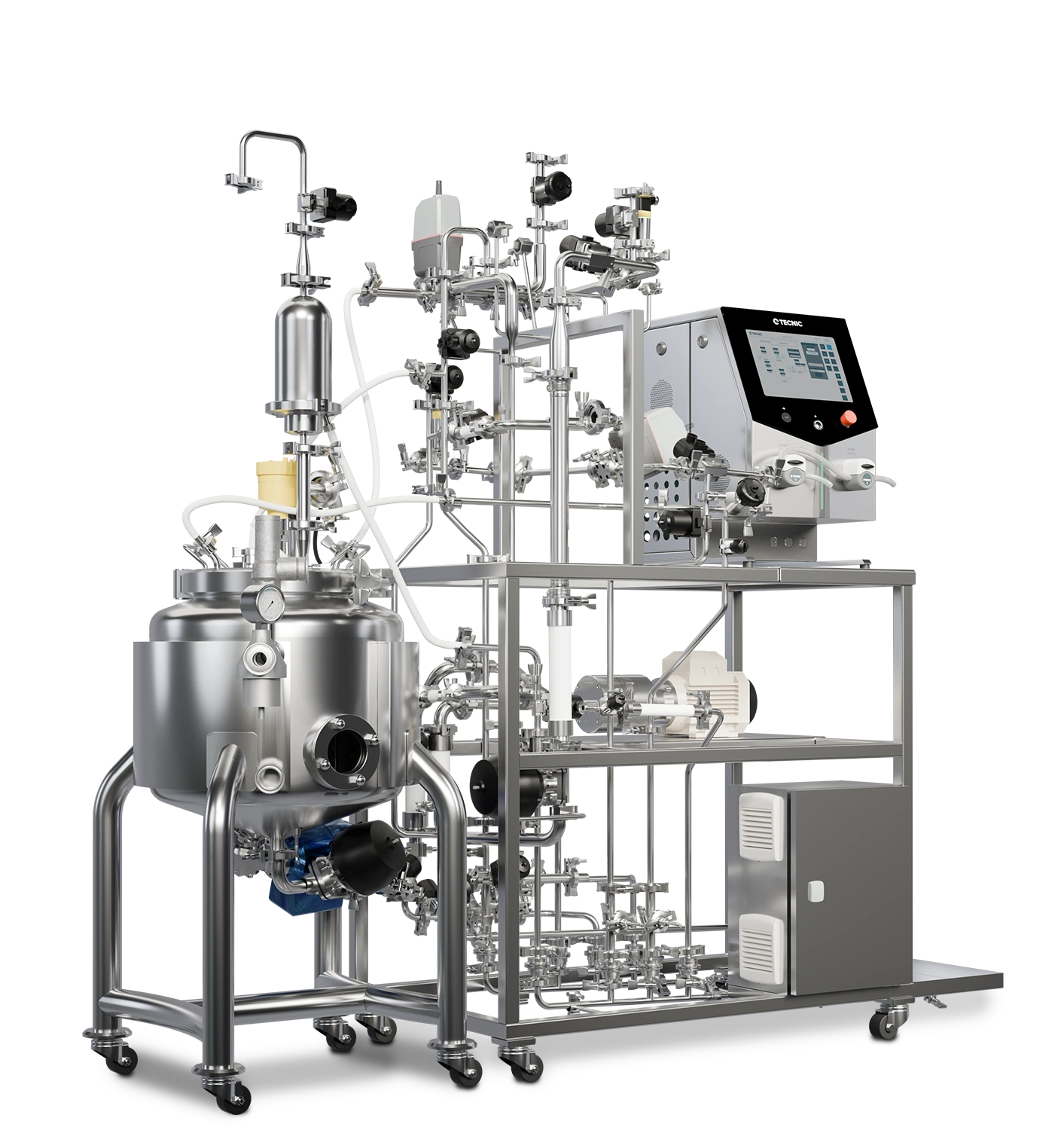
ePilot Bioreactor
Relevant when agitation and circulation strategy need to remain coherent during pilot-scale transfer.
Contact TECNIC
When a process needs a more precise decision on flow pattern and impeller configuration, direct technical discussion is more useful than a generic mixing comparison.
This article works best when flow pattern is treated as a central bioprocess variable, not only as a fluid-mechanics concept.
Frequently asked questions about flow patterns in stirred-tank bioreactors
What is a flow pattern in a stirred-tank bioreactor?
It is the dominant circulation path created by the impeller inside the vessel, which affects mixing, gas dispersion, shear and homogenization.
What is the difference between axial, radial and mixed flow?
Radial flow pushes liquid sideways, axial flow moves it mainly up or down, and mixed flow combines both directions.
What flow pattern does a Rushton turbine create?
A Rushton turbine creates a predominantly radial flow with a strong horizontal jet and two recirculation loops in baffled tanks.
What flow pattern does a pitched-blade impeller create?
It creates a mixed axial-radial flow with diagonal discharge and balanced bulk circulation.
What flow pattern does a hydrofoil impeller create?
It creates a mainly axial flow, promoting strong vertical circulation with relatively low shear.
How do baffles affect the flow pattern in a stirred-tank bioreactor?
Baffles reduce swirl and vortex formation so more impeller power is converted into defined circulation instead of simply spinning the whole liquid volume.
Reviewing which flow pattern best fits your bioreactor process?
Explore TECNIC’s bioreactor solutions or speak with our team to review the right agitation and circulation strategy for your culture and scale-up path.


